Toen me motor werd gereviseerd heb ik bij Dave Goerend een offerte aangevraagd omdat ik eigenlijk meteen me bak wou aanpakken zodat die meer vermogen aankon. Maar dat zou te lang duren en dus zat me motor er alweer in.
Ook had ik gevraagd of hij kan uitleggen hoe die bakken werken.
Toen kreeg ik dit ook.
Heel misschien heb je er wat aan. Het is toch dezelfde bak.
Citaat:
Here is some information on our transmissions, converters, and valve bodies and how they work. It is probably more info than you need, but better more than not enough. If you have any questions, or if I failed to answer something, just let me know.
To make these transmissions stand up to the torque of the Cummins Diesel engine will depend on a few things. The first question has to be: what is the truck used for? A truck that is used for a daily driver only, and with an engine that has not had the power turned up, will not need the same transmission as one built to tow with gross weights of 20,000 pounds plus and 800 lbs ft. torque with 450 horse power or a full race trans. A brief description of our different transmissions follows:
We like to start with a low stall triple disc converter that will keep the engine in its torque range of about 1700-2200 rpm, or put another way, the converter will have the engine working at about 500-800 rpm lower than a stock converter. The stock converter usually lets the engine rev to 2300-2800 rpm, this is past its peak power rpm. On the 24 valve engines and the Common Rail this torque range will be higher.
To explain how a torque converter works, let’s start with 2 wall fans facing each other, (a drive fan and a driven fan). If we turn one fan on, the wind from this fan will make the
other fan turn. In the case of a torque converter, the drive fan is bolted to the engine and the driven fan is connected to the input shaft of the transmission. When we are at a stop sign, with the trans in gear and the engine at idle, the drive fan is spinning so slow that is will not “blow” enough oil at the driven fan to make it turn. As we increase engine and drive fan rpm, it blows more oil at the driven fan and the driven fan starts to turn and moves the vehicle.
The drive fan ALWAYS goes a little faster than the driven fan, just like the wall fans. If you would stick a feather or straw into the driven fan blades it would slow the driven fan down but not the drive fan. This would be just like pulling a heavier trailer. (The straw in the driven fan would be just like adding a load. A heavier trailer is more load.)
When we get up to speed, we have a lock up clutch that will “lock” the fans together. (It actually locks the driven fan to the front cover, which is bolted to the engine. The driven fan is now “locked” to the engine.)
When the drive and driven fan are not locked together, heat is generated in the converter. The greater the load and rpm difference, the greater the heat generated.
Lets say, we have a converter that the drive fan (impeller) is going 2500 rpm and the driven fan (turbine) is going 1800 rpm, (efficiency would be 72%, 1800 divided by 2500)
this efficiency is constantly varying depending on the rpm of the converter, the power input to the converter and the output load, or towed weight).
When the converter clutch locks the fans together, the engine rpm will drop 700 rpm. ( 2500 – 1800 )
If we use a converter that is more efficient, like a “low stall” converter, say 88%, the impeller would be going 2500 rpm and the turbine 2200 rpm, then when the converter clutch locks the turbine to the front cover, the rpm will drop only 300 rpm. This is much easier on the converter clutch lining and will reduce glazing of the clutch lining, and because the fluid coupling of the converter is more efficient it will deliver more power to the wheels before the converter locks up.
To explain the “stall speed”, let’s start with true full stall. If we put the Trans in drive and hold the brakes so the vehicle will not move, and then hold the throttle at wide open, the torque converter will “stall” the engine at a certain rpm, the engine will not be able to spin any faster unless the vehicle is allowed to move. This is true full stall.
WE DO NOT RECOMMEND TESTING TRUE STALL, AS IT CAN DAMAGE SHAFTS AND OVERHEAT THE TORQUE CONVERTER.
The next stall speed can be called “break away” stall speed. Let’s imagine we are stopped on a hill and rather than hold the vehicle stationary with the brakes, we do it by giving it enough throttle so we don’t move forward up the hill OR backwards down the hill. Let’s say, the engine rpm required to “hold” the truck there is 1100 rpm. If we
increase the rpm to 1125 and the truck starts to move up the hill, the “break away” stall speed was 1125 rpm.
“Flash stall” is when you floor the throttle from a standing start… The engine starts to accelerate quickly, then the engine rpm “pauses” and starts to pull the truck. Let’s say the engine gets from idle to 1500 rpm in 1.5 seconds when you floor it, then it takes another 2 or 3 seconds to get from 1500 to 1700 rpm, this would mean the “flash stall” was 1500 rpm. When we lower the stall we want to lower the break away speed and the flash stall speed. This makes the engine work at a lower rpm for a given road speed and in most cases, will increase fuel mileage because the converter is more efficient.
Once we are up to speed, the computer will command the lock up clutch “on”, and the driven fan will lock to the front cover of the converter. Now the drive and driven fan will be going the same speed as the engine and all the engine power will be delivered to the Trans and back to the wheels.
In a stock torque converter, the clutch has 1 clutch plate with about 37 square inches of clutch lining. We like to use 3 clutch surfaces that total about 105 square inches of lining and call this a triple disc converter. This triple disc will hold much more torque than a single disc can.
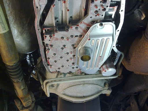
The front band apply piston cover often gets worn and can leak oil pressure when the Trans is in 3rd gear. This cover has a hole in the center and the 2nd band apply pin goes through this hole and pushes on the lever that applies the band. This lever acts just like a rocker arm on the engine and the apply piston cover acts like the valve guide in the cylinder head and holds the apply pin from moving off center. When the apply pin strokes, it will “scrub” on the lever at the contact point just like the valve stem will scrub on the rocker arm. This happens because the valve stem and the apply pin move straight up and down, while the
lever or rocker arm will travel in a circular arc at the contact point. This makes the hole in the cover wear just like a valve guide would wear. If we use a “roller tip” rocker arm, the valve guide will last much longer. In the Trans we use a new cover to eliminate the leakage caused by this type of wear.
The valve body we build will fill the torque converter in all gears, including park so the front bushing of the Trans will get oil while the engine is idling. The lube circuit is modified so there is always line pressure feeding the lube circuit. With the factory valve body, if the Trans fluid gets hot, you may lose oil to the lube circuit while decelerating downhill while the engine is at low rpm or idle and the Trans pump can’t keep up. With our valve body, this will not happen.
Our valve body will have pressures starting at 60-85 psi at idle and will go to 150-195 psi at wide open throttle. (The factory valve body has pressures of about 50-60 psi at idle and 85-95 psi at wide open throttle.) While our pressure is much higher than stock, we try to retain a smooth shift. We do not like a firm bang shift.
This valve body uses the stock manual valve so there is less chance of rear clutch burn up from accidental apply in reverse or neutral.
This valve body is capable of lockup in 3rd, and 4th, 2nd, 3rd and 4th, or all forward gears. 1st, 2nd, 3rd, and 4th if desired, via a toggle switch. This is for use with an exhaust brake or to keep the transmission temp down while towing uphill.
( all ’03 and newer 48RE valve bodies are capable of converter lock up in ALL forward gears )
Also, if drag racing, you can turn the lockup switch on at the starting line and the converter will lock when it shifts to 2nd. If sled pulling, you may want it to lock in 1st also
Our complete transmission comes with the above torque converter and valve body. The 1-2 lever is replaced with a stronger version made of 4140 steel.
Our transmission comes with a new Dodge input shaft and hub (this is not a billet shaft, but it is new, we do have billet shafts available if needed.)
All bearings are replaced with new Torrington bearings including the output shaft roller bearing.
A new overdrive sun gear is installed with the late style bushings that will force lube oil out to the gear teeth.
New snap rings are installed in the front & overdrive clutch.
All new seals & gaskets are installed with updated versions.
A new release spring is installed in the rear clutch.
We install a steel front planet gear in all Diesel and V-10 transmissions. Early models (1995 and earlier) may have come with an aluminum front planet.
The intermediate shaft is a stock Dodge shaft with the dual lube holes for the overdrive section
9310 billet shaft available
The overdrive planet gear is the late design 15* angle with the large lube slots cut into the carrier frame to allow more lube oil to get to the planet pins.
The overdrive direct clutch is the 10 plate design with the larger apply spring.
The overdrive clutch is the 5 plate design.
The Trans case is drilled for extra lube to the rear one way roller clutch.
All parts are inspected, assembled and installed in the Trans.
The transmission is then dynamometer tested, all hydraulic pressures are checked, cooler flow and pressure is checked and the unit is checked for noise in all gears. The park gear is checked, neutral safety switch checked, and then the fluid is drained and inspected. The Trans pan is inspected for any unusual debris and the Trans is dyno tested again and checked for leaks and all electrical components are tested under load.
The above Trans is our base transmission. It is a reliable transmission for engines up to about 400 hp and gross loads up to about 20,000 lbs including truck and loaded trailer. For trucks that are towing in the mountains a billet input shaft should be used.
We also have billet front drums and output shafts available if needed
The input shaft and hub is new and we have very little breakage problems when the trans is not overloaded (20,000 lbs or less gross weight of truck trailer and load) BUT any type of racing can break shafts.
Hopefully, this answers most questions. It may be more information that needed, but I wanted to explain as much as I could. I would be more than happy to answer any questions, or give me a call if you like.
Thanks.
Dave Goerend
563 778 2719